Game
Blinking LED : How to Make Blinking LED With 4 Cool Methods
The Blinking LED circuit is a cleverly designed circuit that is crafted to illuminate LED lights in a mesmerizing pattern, akin to the vibrant display of a digital screen, creating captivating images or texts.
This delightful Christmas decoration lamp boasts a whimsical and unpredictable blinking pattern, adding an extra touch of magic to your holiday decor. Designed with the sole intention of making LEDs dance and twinkle, it brings a festive ambiance to any space.
LED, an abbreviation for Light Emitting Diode, represents a fascinating diode variant within the realm of power electronics. With its unique capabilities, this remarkable device functions as a gatekeeper, preventing the flow of current in the wrong direction while facilitating the smooth passage of current in the intended direction.
LED lights can be flashed through a myriad of techniques, ranging from the utilization of a basic relay to the incorporation of a Schmitt Trigger Inverter, diverse logic gates, microcontrollers, transistors, or even a fusion of transistors and microcontrollers.
During this period, our attention will be directed towards the prevalent and efficient techniques, encompassing relay, transistor, microcontroller, and the amalgamation of a microcontroller with a transistor.
In contrast to regular diodes, an LED illuminates as long as a forward current flows through it, until the current ceases. The minimum operating current of an LED varies depending on its size, and there is also a current threshold beyond which it may break if the forward current becomes excessively high.
Control Blinking LED with Simple Relay
The relay, an essential electromagnetic gadget, serves primarily for automated switching. With the capability to control significant currents using minimal current, it provides a reliable means of activation or deactivation.
At its core, this contraption consists of two essential components – the electrified coil, resembling a fleeting magnet, and a lever-like contact adorned with a resilient spring, poised to retract.
When a minuscule amount of current electrifies the coil, it assumes the role of a magnet, irresistibly attracting the contact towards itself.
Once the coil ceases to be energized, the enchanting magnetic force vanishes, prompting the resilient spring to gracefully retract the contact.
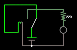
In Fig.2, behold the utilization of a humble relay featuring prominently. Present within this configuration are a relay, a resistor, a direct current (dc) source battery, and a luminous LED.
 |
| Fig.2 LED is turned off and coil is energized |
The circuit depicted above represents the coil in its dormant state, before the battery has infused it with energy.
 |
| Fig.3 LED is turned ON and coil is not energized |
When the coil is electrified and exerts force on the contact, the current is subsequently transmitted to a solitary LED in the depicted circuit.
Once the contact transfers the current to the LED, the coil fails to receive any energy, causing the circuit to revert back to its original state as depicted in Fig.2. This continuous loop of events is illustrated in Fig.4.
 |
| Fig.4 Blinking LED simple circuit with relay |
In order to slow down the LED transition, a clever approach is to employ a time delay mechanism incorporating a resistor and a capacitor. This delay technique utilizes the charging principle of a capacitor, as illustrated in Figure 5.
 |
| Fig.5 Blinking LED with time-delay relay |
Transistor for Blinking LED
The active and cut-off regions of a transistor can be harnessed to function as a switch. In this instance, we will employ an npn transistor to create a captivating sequence of flashing LEDs. Prior to delving into the demonstration, it is imperative that you possess a comprehensive understanding of the functioning of transistors.
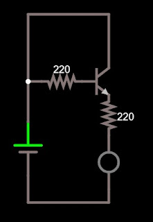
Let’s dive into the world of creativity with Fig.6, where we embark on a journey of exploration using a solitary resistor, an illuminating LED, another resistor, and a mighty dc voltage source.
 |
| Fig.6 Simple example of LED controlled transistor |
As the electric current courses through the base terminal of the transistor, it sets in motion a current that travels from the collector side to the emitter side, resulting in the illumination of the LED.
To ensure optimal performance, the current flowing through the base should surpass the minimum requirement, while the LED will experience a voltage drop of roughly 0.7 V. As illustrated in Fig.7, the LED will then radiate its radiant glow.
 |
| Fig.7 LED emits light |
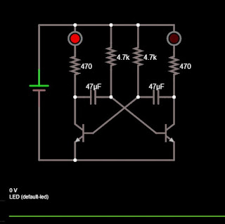
Let’s embark on an exciting journey of synchronizing the rhythmic pulsation of two LEDs by employing a duo of capacitors and LEDs, as depicted in the captivating Fig.8.
 |
| Fig.8 Blinking LED with transistor |
In the illustration provided below as Fig.9, we are presented with the initial phase of the cycle. Initially, the transistor Q1 (located on the left side) takes the lead, igniting LED1 by harnessing the complete current emanating from a voltage source.
LED1, the leftmost resistor (R1), and the collector-emitter terminal of transistor Q1 will all experience the flow of electric current.
 |
| Fig.9 The LED1 flashed |
Fig.10 below displays the subsequent segment, where a current will gracefully flow through LED2, resistor R4 (the resistor situated on the top right), and proceed to charge the capacitor C2 (the capacitor positioned on the right side) until it reaches its maximum capacity.
As the first LED blinked, a fleeting moment passed before this event unfolded.
 |
| Fig.10 Capacitor C2 is charged |
When seeking a peaceful moment, the VBE (base-emitter voltage) dips below 0.7 V, causing LED1 to extinguish gracefully upon Q1’s deactivation.
As we progress to Q2, a fascinating transformation occurs – the LED2 springs to life, emitting a luminosity reminiscent of the captivating illustration showcased in Fig.11.
 |
| Fig.11 The LED2 grows brighter |
Input: As LED1 goes through its colorful cycle, LED2 simultaneously intensifies, while C1 diligently charges until reaching its maximum capacity. The moment Q2 switches off and VBE drops below 0.7 V, LED2 extinguishes, bringing an end to its radiant display.
 |
| Fig.12 Capacitor C1 is charged |
The never-ending cycle continues as depicted in Fig.9, while the complete cycle can be observed in the captivating Fig.13 just below.
 |
| Fig.13 Blinking LED with transistors |
Discover the fascinating world of Kirchhoff’s circuit laws, a captivating topic worth exploring.
Blinking LED Circuit with Microcontroller
Mastering the art of LED blinking can be effortlessly achieved through the utilization of a microcontroller. This ingenious device not only grants the ability to conjure up an array of mesmerizing patterns but also bestows the power to manipulate the intervals at which the blinking occurs.
In this instance, we will employ the fundamental ATMEGA8535 to create a captivating light show by blinking 8 LED in various captivating patterns using the most straightforward technique available.
Illustrated in Figure (14), we present a vivid example showcasing the utilization of a basic ATMEGA8535 microcontroller adorned with eight luminous LEDs, each accompanied by its corresponding resistors.
 |
| Fig.14 ATMEGA8535 and blinking LED |
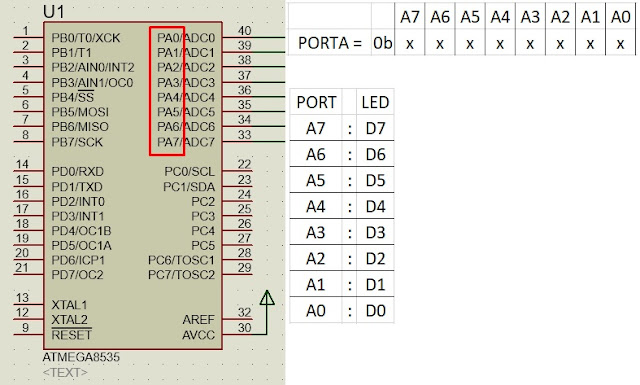
Naming the LEDs from D0 to D7, we establish a sequence from the rightmost LED to the leftmost LED. Employing PORT.A as our output, we transmit a 5 V voltage to the designated LEDs, resulting in their captivating flashes.
To wield authority over the LED, a fundamental grasp of the binary numerical system is imperative for programming purposes.
With 8 output ports, PORT.A presents a biner code.
PORT.A = 0bxxxxxxxx;
Transforming x into either 0 or 1 is a possibility.
When the value of x is changed to 1, the LED that is connected starts to flash. Conversely, altering x to 0 causes the connected LED to extinguish.
Let’s take a look at Fig.15 below to determine the ports that require programming.
 |
| Fig.15 Microcontroller and LED |
Upon examining Fig.14, we discern that the connection between PORTA.0 (PA0) and LED1 (D0) exists, while PORTA.1 (PA1) is linked with LED2 (D1), and this pattern continues.
The binary expression PORTA = 0bxxxxxxxx symbolizes the sequential arrangement of ports A7, A6, …. And A0, in a code known as “biner”.
Input: Assume we desire to illuminate LED D0, which is connected to A0. To achieve this, we can create a program line like so:
PORTA=0b00000001;
Let’s switch off D1 through D7 and exclusively activate D0.
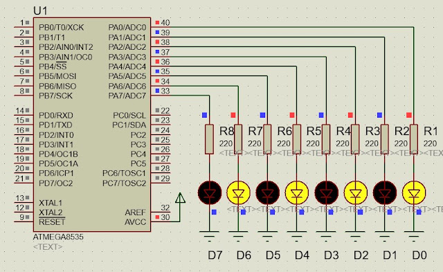
Should we desire to create a mesmerizing LED display, reminiscent of the captivating pattern illustrated in Fig.16,
 |
| Fig.16 Flashing LED in order |
The art of composing binary code is our expertise.
PORTA=0b01010101;
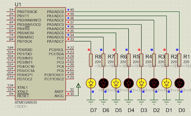
Mirroring the arrangement showcased in Fig.17,
 |
| Fig.17 Flashing LED in opposite pattern |
Let’s transform the code into something new:
PORTA=0b10101010;
In Fig.18, we can merge the two patterns from the previous example into one seamless pattern.
 |
| Fig.18 Blinking LED with microcontroller |
Behold, the code shall manifest itself as follows:
While(1){PORTA=0b01010101;delay_ms(100);PORTA=0b10101010;delay_ms(100);}.
In order to establish a pattern switching interval of 100 milliseconds, we incorporate the ‘delay_ms(100)’ function. Additionally, we employ the ‘while(1)’ loop command for continuous execution.
Microcontroller Blinking LED with Transistor
Occasionally, we employ this technique for a unique scenario, like a larger LED that demands a greater amount of electrical current.
It is common knowledge that the majority of microcontrollers only offer an output voltage of 5 V.
To illuminate a larger LED, a heightened output voltage is required. To achieve this, we can employ an npn transistor in conjunction with an external voltage source and an LED, as depicted in the accompanying Figure (19).
 |
| Fig.19 Blinking LED with transistor-controlled microcontroller |
To create a captivating program sequence akin to the prior microcontroller example, all that is required is the incorporation of a transistor and an external voltage source.
